
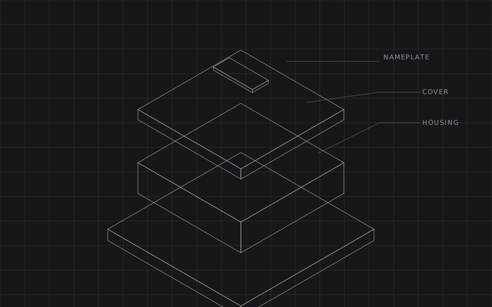
The demo
Scroll past it and it separates. Drag the slider to take manual control, or press play for a timed sweep. The callouts arrive as each part clears the stack.
A studio piece, not client work. The assembly is a generic two-stage gearbox because the technique is the subject, not the product.
Why not a video
Exploded views are how manufactured products get explained, and on the web they almost always arrive as video. That is a defensible default and it has four costs that compound on a marketing page.
- Weight. In our experience a short, clean exploded-view render is two to eight megabytes. This is 13.5 kilobytes of source, which ships minified at 6.9 and gzips to 2.9.
- It cannot be scrubbed meaningfully. A video has a play head; a diagram wants a position. Readers do not want to watch your animation, they want to stop it at the part they care about.
- Text inside video is unreadable and uncrawlable. Part callouts baked into frames are illegible on a phone and invisible to search. Here the callouts are real
<text>in the DOM. - It goes stale. A change to the product means re-rendering and re-encoding. Here it means editing a row.
Video wins when there is material behaviour to show — fluid, deformation, a real machine running. For a rigid assembly coming apart along fixed axes, it is the expensive way to lose the interaction.
Two lines of projection
All the isometric geometry on this page comes from one pair of functions:
function px(x, y, z) { return (x - z) * Math.cos(Math.PI / 6); }
function py(x, y, z) { return (x + z) * 0.5 - y; }
That is the entire 3D pipeline. Every part is described in world coordinates — x and z across the floor, y up — and projected through those two lines.
Boxes draw as three faces: the top, the +x face and the +z face, which are exactly the three a camera in this position can see. Filling them opaquely and drawing bottom to top gives correct occlusion for free — a painter's algorithm, which is sufficient because the parts are stacked, not interleaved.
Round parts are the pleasing bit. A circle drawn in the x–z plane and pushed through the same projection becomes the correct isometric ellipse, at the correct angle, with no special case. Gear teeth are the same loop with the radius alternating. Nothing in the code knows what "isometric" means; the projection does it.
The stagger is the storytelling
An exploded view where everything separates at once is a mess. What makes it legible is that the parts leave in disassembly order — nameplate, bolts, cover, gasket, shaft, gears, housing — the order a technician would actually work in.
Each part therefore carries a window on the master timeline:
{ id: 'cover', kind: 'box', hw: 58, hd: 58, y0: 49, h: 11,
  rise: 244, from: 0.22, to: 0.70 }
The cover starts moving at 22 % of the sweep and settles at 70 %, travelling 244 units. A part higher in the stack always has the earlier window and the longer travel, which is what guarantees nothing ever passes through the part above it. Overlapping the windows is what stops it looking like a machine gun; a part is always in flight, but never all of them.
Each window is eased with the design system's own curve — cubic-bezier(.2, 0, 0, 1), decelerating, no overshoot — so parts arrive at their exploded position and stop dead. Nothing in this brand bounces, including a bolt.
Scroll-scrubbing without hijacking the page
The usual implementation pins the illustration with position: sticky inside a tall spacer, so the reader scrolls "through" the animation. It looks impressive and it takes the scrollbar away from the reader, which is a poor trade on a page they came to read.
This version does something duller and better: the illustration reads its own bounding rectangle and maps its position in the viewport onto the timeline. Progress runs from 0 to 1 as the card travels from the lower part of the screen to the middle. The page scrolls at its normal speed. Nothing is pinned, nothing is trapped, and the reader can scroll straight past.
Two details keep it honest. Scroll handling is passive and coalesced into a single requestAnimationFrame, so no layout work happens per scroll event. And the moment anyone touches the slider, scroll stops driving — an input the reader chose beats an input they did not.
Where this earns its place
We reach for this when a product needs explaining rather than inspecting:
- Machinery and equipment: what is inside, in what order, and which parts are serviceable.
- Installation and assembly sequences — the same scalar can run a step-by-step guide.
- Building services and system schematics, where a section drawing is already the industry's language.
- Any spec sheet where the parts list and the picture currently live in two files and disagree.
When the customer needs to see their configuration in materials and light, this is the wrong tool and a real-time 3D configurator is the right one. Those two pieces answer different questions, and the expensive mistake is building the second when the first would have done.
Questions
It is, when it hijacks the scroll — pinning the viewport, changing scroll speed, or trapping the reader until an animation finishes. This demo does none of those. The page scrolls at exactly its normal rate and the illustration simply reads its own position in the viewport. Under prefers-reduced-motion scroll stops driving it: the illustration opens part-way, the slider takes over, and scroll only comes back if the reader presses the Scroll button themselves. The reader is never moved by something they did not ask for.
Because an exploded view is a diagram, not a photograph. Isometric projection has no perspective foreshortening, so a part is the same size wherever it sits — which is the property that makes technical illustration legible. It is also two lines of arithmetic instead of a scene graph, a camera, lighting and a WebGL context. When the product genuinely needs to be inspected rather than explained, use 3D; that is what we did for the Powertechnic configurator.
That is the point of generating the geometry from a table. The parts list in the demo has an id, a shape, dimensions, a rest height and a travel distance per part. Sourcing those rows from a BOM in an ERP rather than from a literal in the file is a small change, and it means the illustration cannot drift from the product it documents.